NLM Home Page VHP Home Page


Up: Title Page Index: Full Text Index Contents: Conference Page 

Image Index


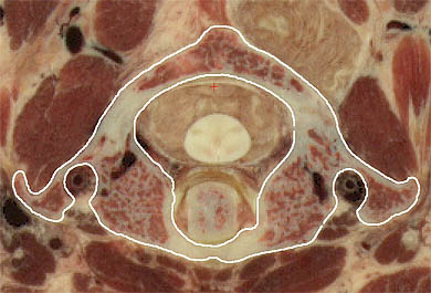
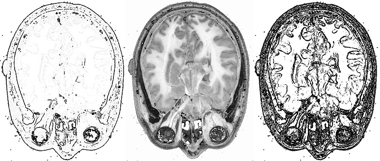
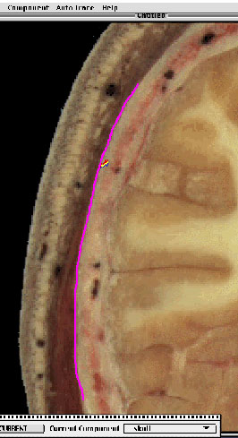
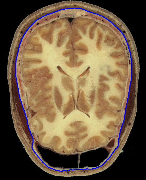
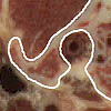
  Figure 1. Trace the outline of the vertebra in the imagery.

  Figure 2. Triangulation between the vertebra's contours on adjacent layers.

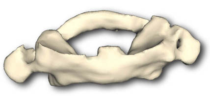
  Figure 3. Create an overall mesh from all the pairs of contours.

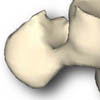
   Figure 4. Render the structure using various computer graphics techniques.
The four basic steps for generating a model of the first cervical vertebra.
 

classical edges

  Figure 5. Edge detection.
 

bunch 'o pixels

  Figure 6. Edge profile.

The Truth

  Figure 7. Traced contour.
 

choices to be considered

  Figure 8. Determining the following pixel belonging to the contour.
 

training set

  Figure 9. The initial interaction of human and system, in tracing the outer surface of the skull.
 

neural net parameters

  Figure 10. The pull-down menu used to set and monitor parameters of the system; the alternating red and green boxes are graphical depictions of the weights between the neural net's layers. 
 

a completed trace

  Figure 11. An example of a semi-automated trace.
 

Ground Truth Trace

  Figure 12. A network-drawn contour (in magenta) superimposed on a manually-drawn contour (in blue).
 

error stats

  Figure 13. The graphs attempt to capture the difference between the two traces over the whole of the head at one level. 
 

whoops! an override...

  Figure 14. Example of where an operator would override the system, at a bump in the skin (where head restraints were placed).


Up: Title Page Index: Full Text Index Contents: Conference Page