

|
|
1. Trace the outline of the vertebra in the imagery
(figure 1).
2. Triangulate between the vertebra's contours on adjacent layers
(figure 2).
3. Create an overall mesh from all the pairs of contours
(figure 3).
4. And finally, render the structure using various computer graphics techniques
(figure 4).
A key issue in working with the Visible Human imagery is the vast amount of data to process. Tracing tissues over many levels in the high-resolution photographs is both time consuming and often boring, especially for large, well-defined areas. The second through fourth steps have been largely automated; the first step however remains a manual task, despite the research in edge detection over the past decades.
The current state of the practice for delineating regions of interest in medical imagery is an expert's manual outlining of the region. In [1] authors note: "Although image segmentation and contour/edge detections have been investigated for quite a long time, there is still no algorithm that can automatically find region boundaries perfectly from clinically obtained medical images ... most segmentation tasks require certain background knowledge about the region(s) of interest."
We have observed two key problems when trying to use methods from the edge-detection literature to automate this task:
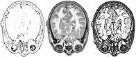 Consider
figure 5 at right to illustrate the first point: the center image shows
a grey scale cross-section through the head. The image on its left
shows the head after a classical edge detection algorithm has been run:
many of the edges are indistinct or only partially connected. If
the edge detector is set to a higher sensitivity, the edges are now more
connected (on the right), but there is now a clutter of other minor edges.
If a tracer's task was to outline the cortex, in either case there is much
work to do in either connecting edges or filtering out unwanted clutter;
tracers found it faster to simply outline the cortex by hand rather than
adjust and filter identified edges. Similarly, (
Consider
figure 5 at right to illustrate the first point: the center image shows
a grey scale cross-section through the head. The image on its left
shows the head after a classical edge detection algorithm has been run:
many of the edges are indistinct or only partially connected. If
the edge detector is set to a higher sensitivity, the edges are now more
connected (on the right), but there is now a clutter of other minor edges.
If a tracer's task was to outline the cortex, in either case there is much
work to do in either connecting edges or filtering out unwanted clutter;
tracers found it faster to simply outline the cortex by hand rather than
adjust and filter identified edges. Similarly, (
 In addressing our second point above, consider the sketch at left (figure 6) of a green
region meeting a white region, where each small square represents an enlarged
pixel. If you were to classify the pixels as either edge or non-edge
pixels, which would you identify as the edge pixels? Classical edge
detection techniques will always identify, more or less, the medium green
pixels as the edge pixels, those in value between the dark green and white
areas.
In addressing our second point above, consider the sketch at left (figure 6) of a green
region meeting a white region, where each small square represents an enlarged
pixel. If you were to classify the pixels as either edge or non-edge
pixels, which would you identify as the edge pixels? Classical edge
detection techniques will always identify, more or less, the medium green
pixels as the edge pixels, those in value between the dark green and white
areas.
But that assumption, reasonable as it seems, leads to trouble in practice. For example, what if the sensors that captured the image were sensitive to green, and the saturated sensors interfered with their neighbors, causing false green readings? In that case, the true edge is perhaps one or two pixels down from the medium green pixels (as shown in figure 7), and no general edge detector would ever identify pixels in the uniform dark-green area as edge pixels. But a person aware of this saturation problem could consistently trace two pixels in from the edge to compensate for it. (A custom-designed detector could do the trick, but our search is for flexible, general solutions).
Our approach to boundary tracing is to watch and then mimic a human tracer. Here's the summary scenario: